NXP公司的LPC5410x系列产品是32位ARM Cortex-M4F/M0+ MCU,集成了104KB SRAM,512KB闪存,3个I2C,2个SPI,4个USART,32位计数器/定时器以及SCTimer/PWM和12位4.8MSPS ADC,具有低功耗,增强调试特性和高级支持区块等系统增强特性,适用于嵌入式应用.
The LPC5410x are ARM Cortex-M4F based microcontrollers for embedded applications. These devices include an optional ARM Cortex-M0+ coprocessor, 104 KB of on-chip SRAM, 512 KB on-chip flash, five general-purpose timers, one State-Configurable Timerwith PWM capabilities (SCTimer/PWM), one RTC/alarm timer, one 24-bit Multi-Rate Timer(MRT), a Windowed Watchdog Timer (WWDT), four USARTs, two SPIs, three Fast-modeplus I2C-bus interfaces with high-speed slave mode, and one 12-bit 4.8 Msamples/secADC.
The ARM Cortex-M4 is a 32-bit core that offers system enhancements such as low power consumption, enhanced debug features, and a high level of support block integration. The ARM Cortex-M4 CPU incorporates a 3-stage pipeline, uses a Harvard architecture with separate local instruction and data buses as well as a third bus for peripherals, andincludes an internal prefetch unit that supports speculative branching. The ARM Cortex-M4 supports single-cycle digital signal processing and SIMD instructions. The Cortex-M4F is the Cortex-M4 with the inclusion of the 32-bit Floating Point Unit. The ARM Cortex-M0+ coprocessor is an energy-efficient and easy-to-use 32-bit core which is code- and tool-compatible with the Cortex-M4F core. The Cortex-M0+coprocessor offers up to 100 MHz performance with a simple instruction set and reduced code size.
LPC5410x主要特性和优势:
Dual processor cores: ARM Cortex-M4 and ARM Cortex-M0+. The M0+ core runs at the same frequency as the M4 core. Both cores operate up to a maximum frequency of 100 MHz.
ARM Cortex-M4F core (version r0p1):
ARM Cortex-M4 processor, running at a frequency of up to 100 MHz.
Floating Point Unit (FPU) and Memory Protection Unit (MPU).
ARM Cortex-M4 built-in Nested Vectored Interrupt Controller (NVIC).
Non-maskable Interrupt (NMI) input with a selection of sources.
Serial Wire Debug with eight breakpoints and four watch points.
Includes Serial Wire Output for enhanced debug capabilities.
System tick timer.
ARM Cortex-M0+ core (version r0p1):
ARM Cortex-M0+ processor, running at a frequency of up to 100 MHz.
ARM Cortex-M0+ built-in Nested Vectored Interrupt Controller (NVIC).
Non-maskable Interrupt (NMI) input with a selection of sources.
Serial Wire Debug with four breakpoints and two watch points.
System tick timer.
On-chip memory:
Up to 512 KB on-chip flash program memory with flash accelerator and 256 byte page erase and write.
104 KB SRAM for code and data use.
ROM API support:
Flash In-Application Programming (IAP) and In-System Programming (ISP).
Power control API.
Serial interfaces:
Four USART interfaces with synchronous mode and 32 kHz mode for wake-up from Deep-sleep and Power-down modes. The USARTs include a FIFO buffer and share a fractional baud-rate generator.
Two SPI interfaces, each with four slave selects and flexible data configuration.
The SPIs include a FIFO buffer. The slave function is able to wake up the device from Deep-sleep and Power-down modes.
Three I2C-bus interfaces supporting fast mode and Fast-mode Plus with data rates of up to 1Mbit/s and with multiple address recognition and monitor mode. Each I2C-bus interface also supports High Speed Mode (3.4 Mbit/s) as a slave. The slave function is able to wake up the device from Deep-sleep and Power-down modes.
Digital peripherals:
DMA controller with 22 channels and 20 programmable triggers, able to access all memories and DMA-capable peripherals.
Up to 50 General-Purpose Input/Output (GPIO) pins. Most GPIOs have configurable pull-up/pull-down resistors, programmable open-drain mode, and input/output inverter.
GPIO registers are located on the AHB for fast access. The DMA supports GPIO ports.
Up to eight GPIOs can be selected as pin interrupts (PINT), triggered by rising,falling or both input edges.
Two GPIO grouped interrupts (GINT) enable an interrupt based on a logical
(AND/OR) combination of input states.
CRC engine.
Timers:
Five 32-bit general purpose timers/counters, with up to 4 capture inputs and 4 compare outputs, PWM mode, and external count input. Specific timer events can be selected to generate DMA requests.
One State Configurable Timer/PWM (SCT) with 6 input and 8 output functions(including capture and match). Inputs and outputs can be routed to/from external pins and internally to/from selected peripherals. Internally,the SCT supports 13 captures/matches, 13 events and 13 states.
32-bit Real-time clock (RTC) with 1 s resolution running in the always-on power domain. A timer in the RTC can be used for wake-up from all low power modes including Deep power-down, with 1 ms resolution. The RTC is clocked by the 32 kHz oscillator.
Multiple-channel multi-rate 24-bit timer (MRT) for repetitive interrupt generation at up to four programmable, fixed rates.
Windowed Watchdog Timer (WWDT).
Ultra-low power Micro-tick Timer, running from the Watchdog oscillator,that can be used to wake up the device from low power modes.
Repetitive Interrupt Timer (RIT) for debug time-stamping and general-purpose use.
Analog peripheral: 12-bit, 12-channel, Analog-to-Digital Converter (ADC) supporting 4.8 Msamples/s. The ADC supports two independent conversion sequences.
Clock generation:
12 MHz internal RC oscillator.
External clock input for clock frequencies of up to 24 MHz.
Internal low-power, watchdog oscillator with a nominal frequency of 500 kHz(WDOSC).
32 kHz low-power RTC oscillator.
System PLL allows CPU operation up to the maximum CPU rate. May be run from
the internal RC oscillator, the external clock input CLKIN, or the RTC oscillator.
Clock output function for monitoring internal clocks.
Frequency measurement unit for measuring the frequency of any on-chip or off-chip clock signal.
Power-saving modes and wake-up:
Integrated PMU (Power Management Unit) to minimize power consumption.
Reduced power modes: Sleep, Deep-sleep, Power-down, and Deep power-down.
Wake-up from Deep-sleep and Power-down modes via activity on the USART,SPI,and I2C peripherals.
Wake-up from Sleep, Deep-sleep, Power-down, and Deep power-down modes using the RTC alarm.
The Micro-tick Timer can wake-up the device from the Deep power-down mode by using the watchdog oscillator when no other on-chip resources are running.
Single power supply 1.62 V to 3.6 V.
Power-On Reset (POR).
Brown-Out Detect (BOD) with separate thresholds for interrupt and forced reset.
JTAG boundary scan supported.
Unique device serial number for identification.
Operating temperature range 40℃ to 105 ℃.
Available in a 3.288 x 3.288 mm WLCSP49 package and LQFP64 package.
图1.LPC5410x框图
LPC54102传感器处理/运动解决方案
The NXP LPC54102-based Application-in-a-box Sensor Processing/Motion Solution enables a new generation of always-on, context-aware products. The system listens to, monitors, and aggregates data from several sensors and processes this data using complex sensor-fusion software, included in the solution.
NXP has partnered with Bosch Sensortec to offer an integrated solution that makes it easy to incorporate motion/inertia and other sensor data into a variety of end applications.
The solution includes commercial and development licenses for Bosch Sensor Fusion (BSX Lite). The software combines motion-sensor data to get accurate, sensor signals or derived sensory information with minimal memory requirements. It supports 6- and 9-axis motion vectors, and the use of quaternions, heading, and pitch and roll.
This all-in-one solution, based on the ultra low power LPC54102 microcontroller, provides everything needed to bring sensor-based motion and other sensor-processing applications to market quickly.
LPC54102传感器处理/运动解决方案主要特性:
Complete hardware and software design, ready to customize
32-bit LPC54102 Cortex-M4F/M0+ microcontroller
LPCXpresso54102 development board
Sensor Shield Board
LPCOpen software drivers
LPC Sensor Fusion Framework
Bosch BSX Lite Sensor Fusion Library
Software demo
Documentation
LPC54102传感器处理/运动解决方案主要优势:
Add 6- or 9-axis motion sensors to your application
Integrated sensor fusion middleware and portable sensor fusion framework
Sensor Fusion APIs allow users to easily create applications that use motion sensors
Additional digital sensors (pressure/temperature, ambient light, proximity)
Software development tools for a quick start to writing, compiling, and running sensor-based applications
Gives end-product designers access to a rich set of reference design materials, including documentation, porting guide, and schematics
Stackable hardware to support more sensors or add plug-in modules
Large set of pinouts for measurement and prototyping
On-board debugger included
Low power
LPC54102传感器处理/运动解决方案应用:
Tablets, smartphones
Portable fitness, health monitoring
IoT nodes
Asset tracking
Robotics and Unmanned Vehicles
Gaming, entertainment
Pointing Devices
LPC54102传感器处理/运动解决方案包括:
Reference hardware including the LPCXpresso54102 board and a sensor shield with nine sensors and Bluetooth LE wireless connectivity
Bosch BSX Lite sensor fusion middleware
Bosch sensor drivers
LPC Sensor Framework to simplify sensor-processing and support additional sensors
Complete reference documentation
The Solution’s LPCXpresso54102 development board includes:
Large set of pinouts for measurement and prototyping
Built-in Hi-Speed USB debug probe (Link2) and support for external debug probes
On-board 1.8/3.3V or external power supply options for LPC54102
Built-in MCU power consumption and supply voltage measurement for LPC54102 MCU and sensor shield board
UART, I2C and SPI port bridging from LPC54102 target to USB via Link2 probe
The sensor shield board includes:
Bosch Sensortec BMI055 inertial measurement unit, BMC150 digital compass, BMM150 magnetometer, and BMP280 pressure/temp sensors
MAX44000 ambient light/proximity sensor
Vishay VSOP98260 IR remote control sensor/driver
ACKme AMS002 Bluetooth LE module
Headers for easy prototyping of additional SPI and I2C sensors
图2.LPC54102传感器处理/运动解决方案外形图
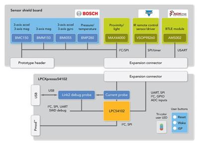
图3.LPC54102传感器处理/运动解决方案框图
图4.LPC54102传感器处理/运动应用软件架构图