基于单片机的直流电机PID调速系统整体硬件设计
SHAPE * MERGEFORMAT
图3-6 基于单片机的直流电机PID调速系统整体硬件结构框图
主要由单片机控制单元、电机驱动电路、霍尔传感器电路构成。
4 直流电机PID系统软件设计 4.1 如何应用PID控制电机转速
基于单片机的直流电机PID调速系统软件设计是基本的设计核心是运用PID调节器,从而实现直流电机的在带动负载的情况下也能稳定的运行。
1. 在单片机中编程设定一数字量为控制直流电机速度的给定值;
2.利用霍尔传感器对直流电机进行测速,并将其转化为数字量作为直流电机的反馈值;
3. 应用数字PID模型作单片机控制编程,其中P、I、D参数可以通过以下增量式PID控制算法得出;具体的PID控制相关参数的计算和仿真如下:
4.1.1 直流电机动态数学模型
直流电机相关参数如下:额定数据:10kW,220V,50A,1000r/min,系统电枢回路总电阻R=1.0![]() ,
,![]() =44,
=44,![]() =0.1925V*min/r,系统运行部分的飞轮惯量
=0.1925V*min/r,系统运行部分的飞轮惯量![]() =10N*
=10N*![]() ,
,![]() =132.8V等等。
=132.8V等等。
SHAPE * MERGEFORMAT
图4-1反馈控制闭环直流调速系统的动态结构框图
由此可见,反馈控制闭环直流调速系统的开环传递函数是:
![]()
式中 :
![]() 。
。
直流电机相关参数计算如下:
![]()
L=0.017H 。
计算系统各环节的时间常数:
电磁时间常数:
![]()
机电时间常数:

又因为:Kp =21
闭环系统的开环放大系数:
![]()
于是,原始闭环系统的开环传递函数是:
![]()
4.1.2 增量式PID控制算法
当执行机构需要的是控制量的增量时,可由下式:
![]() (4-1)
(4-1)
式中:
![]() -----采样序号,K=0,1,2……;
-----采样序号,K=0,1,2……;
![]() ----第K次采样时刻的脚手架输出值;
----第K次采样时刻的脚手架输出值;
![]() ----第K次采样时刻的输入偏差值;
----第K次采样时刻的输入偏差值;
![]() ----第(K-1)次采样时刻输入的偏差值;
----第(K-1)次采样时刻输入的偏差值;
![]() ----积分系数,
----积分系数,![]() ;
;
![]() ----微分系数,
----微分系数,![]() ;
;
![]() ----开始进行PID控制时计算机的输出值。
----开始进行PID控制时计算机的输出值。
导出提供增量的PID控制算式。根据递推原理可得:
![]() (4-2)
(4-2)
用式(2-8)减式(4-2),可得
![]() (4-3)
(4-3)
式中![]() 式(4-3)称为增量式PID控制算法。可将式(4-3)进一步改写为:
式(4-3)称为增量式PID控制算法。可将式(4-3)进一步改写为:
![]() (4-4)
(4-4)
式中:
![]()
![]()
![]()
他们都是由采样周期、比例系数、积分时间常数、微分时间常数有关的系数。
不难看出,由于一般计算机控制系统采用恒定的采样周期T,一旦确定了![]() 、
、![]() 和
和![]() ,只要使用前后3次测量值的偏差,就可以用式(4一3)或(4-4)求出控制增量。
,只要使用前后3次测量值的偏差,就可以用式(4一3)或(4-4)求出控制增量。
采用增量式算法时,计算机输出的控制增量Δu(k)对应的是本次执行机构位置(如阀门开度)的增量。对应阀门实际位置的控制量,即控制增量的积累![]() 需要采用一定的方法来解决,例如用有积累作用的元件(如直流电机)来实现;目前采用较多的是利用算式u(k)=u(k-1)+Δu(k)通过执行软件来完成。
需要采用一定的方法来解决,例如用有积累作用的元件(如直流电机)来实现;目前采用较多的是利用算式u(k)=u(k-1)+Δu(k)通过执行软件来完成。
增量式控制虽然只是在算法上作了一点改进,但却带来了不少优点:
首先,由于计算机输出增量,所以误动作时影响小,必要时可用逻辑判断的方法去掉。
其次,手动/自动切换时冲击小,便于实现无扰动切换。此外,当计算机发生故障时,由于输出通道或执行装置具有信号的锁存作用,故依然能保持原值。
再次,算式中不需要累加。控制增量Δu(k)的确定,仅与最近k次的采样值有关,所以较容易通过加权处理而获得比较好的控制效果。
同时增量式控制也有不少缺点:积分截断效应大,有静态误差;溢出的影响大。因此,在选择时不可一概而论,一般认为在以晶闸管作为执行器或在控制精度要求高的系统中,可以采用位置式控制算法,而在以直流电机或电动阀门作为执行器的系统中,则可采用增量式控制算法。
图4-2给出了增量式PID控制算法程序框图。
SHAPE * MERGEFORMAT
 图4-2 增量式PID控制算法程序框图
根据增量式PID控制算法,设计了仿真程序。被控对象如下:
![]()
%建立系统的离散化模型
s=tf('s');
Gp=tf(55.85/((0.049*s+1)*(0.026*s+1)*(0.0167*s+1)));
Ts=0.00167;
Gpd=c2d(Gp,Ts); %连续系统离散化
%用根轨迹法找出临界值Kcr和Wcr
figure(1)
clf %清除当前图形
rlocus(Gpd); %绘制根轨迹
[K,Poles]=rlocfind(Gpd); %从根轨迹确定临界点对应的增益和极点
Kcr=K;
Wcr=angle(Poles(1))/Ts;
Tcr=2*3.14/Wcr;
%设计PID控制器
%按表中公式确定参数Kp,Ti,Td
Kp=0.388*Kcr;
Ti=0.5*Tcr;
Td=0.125*Tcr;
%按PID控制器模型确定Ki和Kd
Ki=Kp*Ts/Ti;
Kd=Kp*Td/Ts;
disp('PID参数Kp,Ki,Kd分别为:')
Kp
Ki
Kd
%建立PID控制器的离散化模型Gcd(s)
z=tf('z',Ts)
Gcd=Kp+tf(Ki*z/(z-1))+tf(Kd*(z-1)/z);
%检验PID控制器的性能
Gd=Gpd*Gcd;
Gclose=feedback(Gd,1);
figure(1)
clf
step(Gclose,'r')
运行的结果如下:
selected_point =
-3.2749 - 0.0559i
PID参数Kp,Ki,Kd分别为:
Kp =
1.7037e+004
Ki =
1.7045e+004
Kd =
4.2570e+003
Transfer function:
z
Sampling time: 0.00167
PID校正后阶跃响应曲线如图
4-3 PID校正后阶跃响应曲线如图
由此, 我们可在动态仿真集成环境Simulink下构造一个系统模型,并将所求得的![]() ,
,![]() 和
和![]() 代入SIMULINK中,如图4-4所示。
代入SIMULINK中,如图4-4所示。
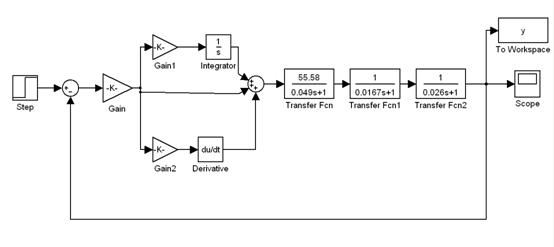
图4-4 控制系统模型图
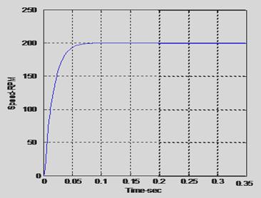
在Simulink窗口下点击开始仿真按钮, 双击SCOPE图标, 就可以得到如图4-5所示的,接入PID控制器后的闭环响应曲线。
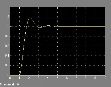
图4-5 PID整定后的阶跃响应曲线
单片机PWM调宽输出作为输出值,通过H桥式直流电机驱动电路等,实现对直流电机的PID调压调速功能。具体应用:
用单片机控制达林顿管使之工作在占空比可调的开关状态,精确调整电机转速。这种电路由于工作在管子的饱和截止模式下,效率非常高;H型电路保证了可以简单地实现转速和方向的控制;电子开关的速度很快,稳定性也极佳,是一种广泛采用的PWM调速技术。我们采用了定频调宽方式,因为采用这种方式,电机在运转时比较稳定;并且在采用单片机产生PWM脉冲的软件实现上比较方便。且对于直流电机,采用软件延时所产生的定时误差在允许范围。最终实现对直流电机的PID调压调速功能。
4.2 调速系统主程序原理框图
SHAPE * MERGEFORMAT
图4-6 调速系统主程序原理框图
4.3 中断服务程序原理框图
SHAPE * MERGEFORMAT
图4-7中断服务程序原理框图
5 结论
本文在广泛查阅资料,了解直流电机特性的基础上,对直流电机的控制原理进行了的研究,设计了一款简单直流电机PID控制器。
本文所设计的基于AT89S51单片机的无刷直流电机控制器具有硬件结构简单、保护功能完善、软件采用模块化设计易于用户二次开发等特点。主要实现了如下功能:
(1)采用AT89S51单片机作为主控芯片,加强对直流电机的智能控制;
(2)安全控制电机系统,利用霍尔元件,实现了系统的速度的反馈控制;
(3)利用PID控制算法对于直流电机加以控制;
(4)关于直流电机的先关参数计算,以及PID参数的获得;
实践证明,本控制系统精度高,稳定性好,硬件简单且工作可靠,具有很好的推广价值。
由于时间与能力有限,本文所设计的控制系统还有待于进一步的改进,比如可采用无位置传感器的控制方法,利用软件检测电机的反电动势,从而省去位置传感器,降低硬件成本,提高可靠性;还可采用专用控制芯片和单片机相结合的方式实现直流电机的控制,使系统具有更好的灵活性和稳定性。
6 致 谢
首先在此表达对指导老师感谢。在做毕业设计这段时间里,指导老师给了我很多指导和建议,让我对直流电机控制系统有了很多了解,并学到了很多对我有用的东西。尽管他带教学课程,工作很忙,但他也抽出自己空余的时间辅导我们,对我们所问的问题均一一细致的解答。
其次还要感谢电气教研室的所有老师,感谢他们对我学习和生活上的支持和帮助,使我在大学期间学到了很多的有用的东西。
最后,忠心的感谢在百忙之中评阅论文和参加答辩的各位领导、教授、老师!
7 参考文献
[1] 康年光.电子技术基础(数字部分).高等教育出版社.2005.07
[2] 刘乐喜.微机计算机接口技术及应用.华中科技大学出版社.2005.08
[3] 谢嘉奎.电子线路(线性部分).高等教育出版社.2004.04
[4] 潭浩强.C语言程序设计.清华大学出版社.2005.07
[5] 李群芳,肖看.单片机原理、接口及应用—嵌入式系统技术基础.清华大学出版社.2005.03
[6] 冯博琴.微型计算机原理与接口技术.清华大学出版社.2004
[7] 长德,李华,李东.MCS51/98系列单片机原理与应用.机械工业出版社.1997
[8] 李群芳,张士军,黄建.单片微型计算机原理与接口技术.电子工业出版社.2002
[9] 石东海等.单片机数据通信技术从入门到精通.西安电子科技大学出版社.2002
[10] 谢自美等.电子线路设计、实验、测试(第二版).华中科技大学出版社.2000
[11] R.L.Geiger,P.E.Allen,N.R.Strader.VLSI.DLSI Design Techniques for Analog And Digital Ciruits.McGraw-Hill Inc.1990
[12] N.R.Mallik.Electronic Ciruits-Analysis Simulation and Design.Prentice Hall,1995.
8 附 录
外文资料
Proportional Integral and Derivative Control of
Brushless DC Motor
Atef Saleh Othman Al-Mashakbeh
Department of Electrical Engineering Tafila Technical University
P.O. Box 179, Tafila – Jordan
Abstract
Brushless DC (BLDC) motors are one of the electrical drives that are rapidly gaining popularity, due to their high efficiency, good dynamic response and low maintenance. In this paper, the modeling and simulation of the BLDC motor was done using the software package MATLAB/SIMULINK. A speed controller has been designed successfully for closed loop operation of the BLDC motor so that the motor runs very closed to the reference speed. The simulated system has a fast response with small overshoot and zero steady state error.
Keywords: PID Controller; BLDC motor; Mathematical model;
1. Introduction
Since the late 1980’s new design concept of permanent magnet brushless motors has been developed.The permanent magnet brushless motor can be classified upon to the back-EMF waveform, where it can be operated in either brushless AC (BLAC) or brushless DC (BLDC) modes. Usually the BLAC motors have a sinusoidal back-EMF waveform and BLDC motors have a trapezoidal back-EMF. In modern electrical machines industry productions the brushless direct current (BLDC) motors are rapidly gaining popularity. BLDC motors are used in industries such as Appliances, HVAC industry,medical, electric traction, road vehicles, aircrafts, military equipment, hard disk drive, etc. Comparing BLDC motors with DC motors, the DC motor have high starting torque capability, smooth speed control and the ability to control their torque and flux easily and independently. In the DC motor, the power losses occur mainly in the rotor which limits the heat transfer and consequently the armature winding current density, while in BLDC motor the power losses are practically all in the stator where heat can be easily transferred through the frame, or cooling systems can be used specially in large machines. In general the induction motor has many advantages as: their simplest construction, simple maintenance, low price and reliability.Furthermore, the disadvantages of induction machines make the BLDC motors more efficient to use and become more attractive option than induction motors. Some of the disadvantages of induction machines are poor dynamic characteristics, lower torque at lower speeds and lower efficiency
2. Dynamic Model of the BLDC Motor
It is assumed that the BLDC motor is connected to the output of the inverter, while the inverter input terminals are connected to a constant supply voltage, as shown in Fig.1. Another assumption is that there are no power losses in the inverter and the 3-phase motor winding is connected in star.
Figure 1: BLDC model
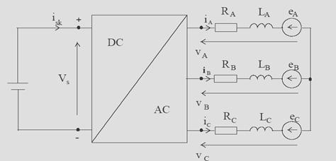
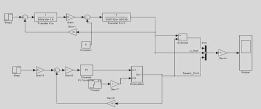
Figure 2: MATLAB simulink of BLDC
For a symmetrical winding and balanced system, the voltage equation across the motor winding is as follows:
Applying Kirchhoff’s voltage law for the three phase stator loop winding circuits yields:
![]() (1)
(1)
![]() (2)
(2)
![]() (3)
(3)
Where the back-EMF waveforms a e , b e and c e are functions of angular velocity of the rotor shaft, so
![]() (4)
(4)
Where Ke is the back-emf constant.
So the BLDC motor mathematical model can be represented by the following equation inmatrix form:
 (5)
(5)
If we assume that the rotor has a surface-mounted design, which is generally the case for today’s BLDC motors, there is no saliency such that the stator self inductances are independent of the rotor position, hence:
![]()
And the mutual inductances will have the form:
![]()
Assuming three phase balanced system, all the phase resistances are equal:
![]()
Rearranging the equation (5) yields;
 (6)
(6)
The electromechanical torque is expressed as
![]() (7)
(7)
But the electromagnetic torque for this 3-phase BLDC motor is dependent on the current, speed and back-EMF waveforms, so the instantaneous electromagnetic torque can be represented as:
![]() (8)
(8)
The simulation of the BLDC motor was done using the software package MATLAB/SIMULINK. After running the simulation, the speed, torque, current, waveforms were recorded and analyzed. Fig. 3 shows the open loop response of the motor.
Figure 3: Open loop response
3. PID Controller
PID control is a proportional integral plus derivative controller whose transfer function is:
![]() (9)
(9)
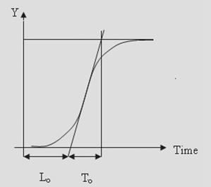
The selection of the Proportional Integral and Derivative (PID) controller parameters can be obtained using the Ziegler-Nichols methods. Depending on the values of as shown in fig. 4 and using the Ziegler-Nichols tables, we can fid the PID parameters.
Figure 4: Zegiler-Nichols PIS Parameters
Now, using the following equations, the PID parameters can be derived:
![]() (10)
(10)
![]() (11)
(11)
![]() (12)
(12)
4. Simulations and Results Analysis
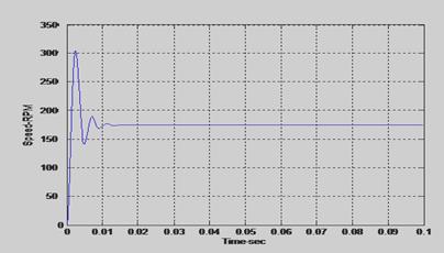
A simulation of a brushless DC motor system with the PID gains calculated using the above equations was performed using MATLAB. The calculated gains of PID control are provided in Table 1. The speed response is shown in Figure 5. So it can be concluded that a direct PI tuning method is suitable to designate self-tuning technique for BLDC motor, where the overshoot in the motor speed response approximately zero and the error steady state is also go to zero.
Table 1: PID Parameters
PID GAINS Values
PID GAINS
Values
Kp
T1
TD
9
0.04
0.01
Figure 5: The motor response using PI controller

5. Conclusions
In this paper, a mathematical model of brushless DC motor is developed. The simulation of the brushless DC motor was done using the software package MATLAB/SIMULINK. Also PID control based on the Ziegler-Nichols method is presented and applied to brushless DC motor. This method is feasible due to the unique and simplified structure of this motor. The PID controller designed has been simulated and observed to have good performance, where the results show that the overshoot before adding the PI control was 71% but after adding PI control the maximum overshoot was approximately zero which is a good result. So a speed controller has been designed successfully for closed loop operation of the BLDC motor and the motor runs very closed to the reference speed.
中文翻译
PID控制无刷直流电机
阿特夫奥斯曼萨利赫铝马沙克贝
电气工程处技术大学Tafila P.O. 179箱,Tafila - 约旦
摘要
无刷直流(BLDC)电机的电驱动器正在迅速普及,由于其高效率,良好的动态响应和低维护1。本文的建模和仿真的无刷直流电机是用软件MATLAB / SIMULINK的。一个速度控制器已经专为无刷直流电机闭环操作成功,使电机的运行速度非常封闭的参考速度。该模拟系统具有超调量小和零稳态误差的快速反应。
关键词:PID控制器,直流无刷电机;数学模型;
1.介绍
20世纪80年代末以来的永磁无刷电机新的设计概念已developed.The永磁无刷电机可分为点名的反电动势波形,它可以在任何无刷交流(双语)或无刷直流(BLDC操作)模式。通常双语电机有一个正弦反电动势波形和直流无刷电机具有梯形反电动势。在现代工业生产的电机无刷直流(BLDC)电机正在迅速获得普及。无刷直流电机应用于行业,如家用电器,暖通空调行业,医疗,电力牵引,道路车辆,飞机,军事设备,硬盘驱动器等比较无刷直流电机与电机,直流电机具有高起动转矩能力,平稳的速度控制并有能力控制自己的转矩和磁通容易和独立。在直流电机,功率损失主要发生在转子从而限制了热量传递,因此电枢绕组的电流密度,而在直流无刷电机的功率损耗几乎在热的地方可以很容易地通过框架,或全部转移定子冷却系统可以专门用来在大型机器。一般来说,异步电机具有许多优点:它们的最简单的建设,维护简单,价格低廉,reliability.Furthermore,感应机的缺点作出更有效的直流无刷电机的使用,成为更具吸引力,异步电机的选择。对异步电机的缺点主要是穷人的动态特性,以较低的速度和低效率,低扭矩
2.动态模型的直流无刷电机
这是假设BLDC电机连接到变频器的输出,而逆变器输入端连接到电源电压恒定,如在图1所示。另一种假设是,有没有在逆变器的功率损耗和3相电机绕组星形连接。
图1:无刷直流电机模型
图2:MATLAB的无刷直流电机的Simulink
对于对称绕组和平衡系统,电机绕组两端的电压方程如下:
申请三相定子绕组电路产量环基尔霍夫电压定律:
![]() (1)
(1)
![]() (2)
(2)
![]() (3)
(3)
凡反电动势波形爱,是和CE是角速度的转子轴,所以功能
![]() (4)
(4)
凡柯是反电动势常数。
因此,无刷直流电机的数学模型可以表示为下列方程式inmatrix形式:
(5)
如果我们假设转子一个表面贴装设计,通常是今天的直流无刷电机的情况下,没有显着性,这样的自我定子电感是转子位置无关,因此:
![]()
而互感将有如下形式:
![]()
假设三相平衡系统,所有的相电阻是相等的:
![]()
重新整理等式(5)产量;
(6)
机电扭矩表示为
![]() (7)
(7)
但是,这种三相无刷直流电机电磁转矩的电流,速度和反电动势波形,所以瞬时电磁转矩可以表示为依赖:
![]() (8)
(8)
作者:无刷直流电机是用仿真软件MATLAB / SIMULINK的。在运行模拟,速度,转矩,电流,波形记录和分析。图3显示电机的开环反应。
图3:开环反应

3.PID控制器
PID控制是一个比例积分加微分控制,其传递函数为:
![]() (9)
(9)
该比例积分微分(PID)的选择控制器参数,可使用齐格勒-尼科尔斯方法。视乎如图所示的值。 4,使用齐格勒-尼科尔斯表,我们可以瞎话的PID参数。
图4:Zegiler -尼科尔斯私立参数
现在,使用以下方程,可以推导出PID参数:
![]() (10)
(10)
![]() (11)
(11)
![]() (12)
(12)
4.模拟及结果分析
一个无刷直流电机系统与PID模拟收益计算使用上述方程,用MATLAB进行。 PID控制计算收益是提供表1。速度响应如图5所示。因此,可以得出结论,直接有价证券调谐方法适用于指定自校正直流无刷电机,其中在电机冲高速响应技术和接近于零稳态误差也到零。
表1:PID参数
联网的PID值
PID的增益
价值观
Kp
T1
TD
9
0.04
0.01
图5:使用PI控制器的运动反应
5.结论
在此,提出了一种无刷直流电机的数学模型。在无刷直流电机是用模拟软件MATLAB / SIMULINK的。此外PID控制的基础上齐格勒,尼科尔斯的方法,提出并应用于无刷直流电机。这种方法是可行的,由于这一独特的电机和简化结构。 PID控制器的设计进行了模拟,并观察到有良好的表现,其中结果表明,在加入PI控制超调为71%,但后加入PI控制的最大超调约为零这是一个很好的结果。因此,一个速度控制器已成功地设计了无刷直流电机闭环运行,电机运行速度非常封闭的参考速度。